Getting Started
Table of contents
Requirements
Hardware requirements:
- MCLV-V2 Motor Control Board
- PIM ATSAME54 with external Op-Amp
- Programmer (PICkit 4, ICD4, Real-Ice, PICkit 3, ICD3, …)
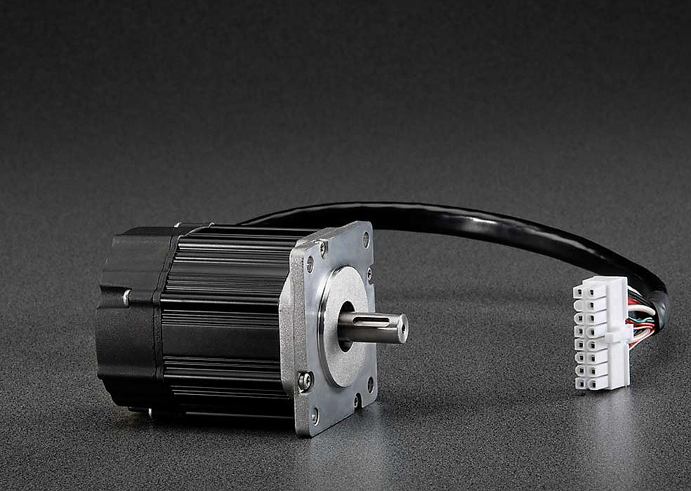
- PMSM motor (N23 Industrial Grade Motors)
- Cable to send data from the MCLV board (Tx) to the PC (Rx) (like a FTDI cable)
Software requirements:
- Matlab/Simulink
- Embedded coder (Matlab Coder & Simulink Coder)
- Fixed point toolbox
- MPLAB device blocks for Simulink
- MPLAB X IDE development (required to flash the binary from matlab)
- XC32 compiler
The verify correct configuration you can use the test program
##
Motor specifications

The proposed motor for this experimentation is a Permanent Magnet Synchronous Motor (PMSM) The (N23 Industrial Grade Motors)
Motor parameters
The motor parameters are :
| Parameter | Value |
|---|---|
| Max voltage | V = 24V |
| Max current | I = 4A |
| Pole pairs number | p=4 |
| Stator resistance | R=0.6 Ohm |
| Stator inductance | L= 0.35mH |
| Flux constant | Phif = 6.6mWb |
| Inertia | J =1.10^-5 kg.m^2 |
| Fluid friction | f = 1.10^-5 N.m.s/rad |
The motor parameters have been identified on-line using the procedure described on the video :
“All In One” motor Parameters Identification and control embedded in a dsPIC DSCs
Further details can be found on the identification procedure can be found in the article available here:
- R. Delpoux, M. Bodson, T. Floquet, Parameter estimation of permanent magnet stepper motors without mechanical sensors, Control Engineering Practice, Volume 26, 2014, Pages 178-187.
The motor is equipped with an incremental encoder. The encoder hat 1000 counts/rev.
Motor connection
The connexion between the motor and the MCLV-V2 is shown below :

Hardware configuration
Pinout of the MCLV-V2 with the PIM ATSAME54 and external Op-AMP
The pinout of the MCLV-2 board with the PIM ATSAME54 and external Op-AMP configuration is described in its Information Sheet.

It is important to verify that External OP_AMP Configuration is plugged :

The table below provide important pinout informations.
| MCLV-2 Board | ATSAME54 |
|---|---|
| LED1 | B27 |
| LED2 | B26 |
| BTN S2 | D9 |
| BTN S3 | D10 |
| UART_Rx | A13 |
| UART_Tx | A12 |
| PWM1 (L/H) | A16 - A8 |
| PWM2 (L/H) | A17 - A9 |
| PWM3 (L/H) | A18 - A10 |
| HALLA / QEA | C16 |
| HALLB / QEB | C17 |
| HALLC / INDX | C18 |
| Pot | A06 |
| Ia | A02 |
| Ib | B08 |
Programmer
Programmers like PicKit or Snap can directly be connected to the PIM ATSAME54 as shown on the picture below.

