Mplab Solution for Simulink
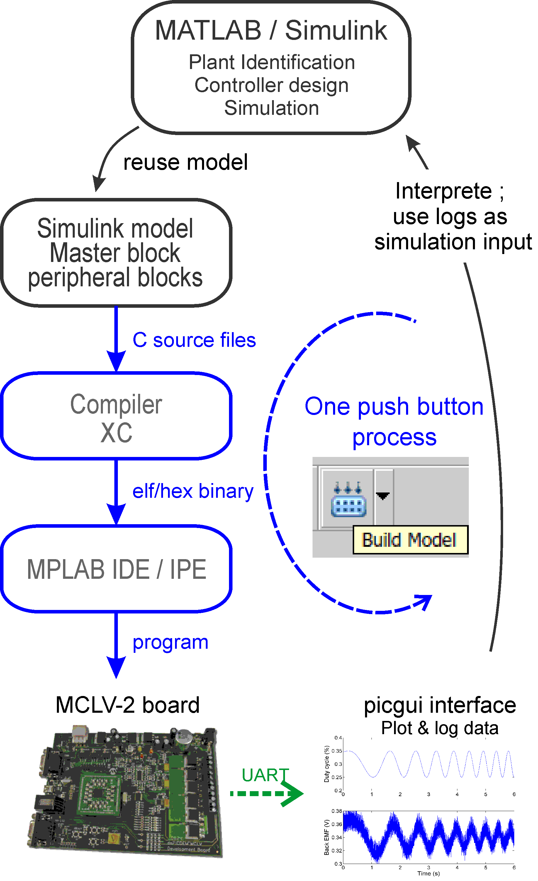
This page details the important steps for the real-time implementation of a multi-rate control law. MPLAB Device Blocks for Simulink enables Embedded Coder for automated build and execution of real-time executable for any board equipped with a dsPIC :registered:, PIC32 :registered: or SAMx7 from a Simulink model. Any model can thus be embedded. To compile the generated code and program the board from the Simulink interface with a single `Build’ push button on top right of the Simulink interface :
Embedded codes need however to respect some constraints.
Discrete time
Simulations are typically performed in the continuous time domain using Matlab/Simulink :registered:. A differential equation solver is used to solve simulation outputs. The real-time embedded software does not implement such solver so a discrete-time equivalent controller must be used.
Multi-rate model
Multi-rate model comprises blocks running at various rates. For each block, it is possible to set its rate and its offset. Blocks rate offset are multiple of the base model time step defined in the solver panel. A multi-rate model can be implemented using a multi-tasking scheduler (default settings) or a single tasking program.
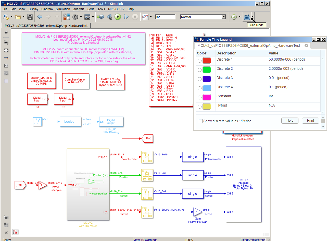
Simulink highlights blocks with colors to represent rates as represented on the figure. This option is displayed by clicking on the “Sampling Time” icon represented by two blue and red arrows.
Single tasking program
In a Single tasking program, all tasks started at a given base model time step must be completed within the end of that time step slot to respect real-time constraints.
Multi tasking scheduler
In a Multi tasking scheduler, a monotonic-rate scheduler is implemented where higher rate tasks have higher priority and interrupt lower task rate which have lower priority whenever required. This multi-tasking scheduler has a simple priority rule which is well suited for automatic. Its limited implementation penalty in execution time worth the gain in flexibility.
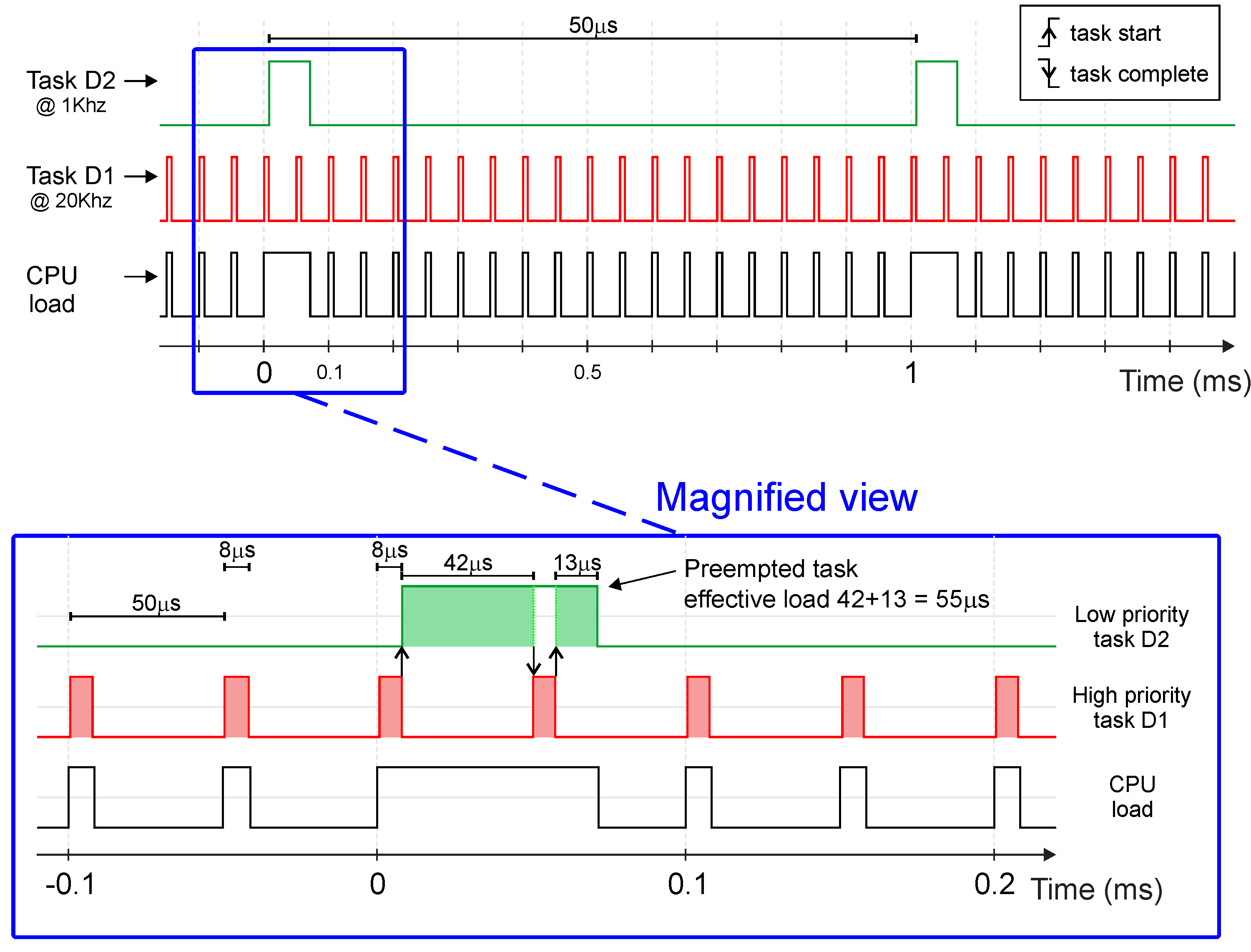
The figure presents a timing analysis for a motor control with the CPU load state (black curve where 1 is busy and 0 is idle state), the fast task D1 (red) and slow task D2 (green) respective start and stop on rising and falling edges.
The lower graph is a magnification of the higher priority task D1 preemption of the lower priority task D2. Note that, the slow D2 task is not cleared when being preempted but exclusively when task is completed. The shaded region in the tasks D1 and D2 shows the CPU execution on each task. This illustrates the benefit of a Multi-tasking scheduler as presented on the Figure.
Code efficiency
The code performance are surprisignly good. Peripheral are handled as in background through interrupts. Peripheral blocks for input peripherals are thus not blocking as they just have to read the last result obtained from that peripheral; keeping the CPU time dedicated to the control algorithm. For example, the base time step is typically triggered by the ADC block end of conversion interrupt thus when the ADC block is evaluated within the algorithm, the conversion results are already available. The ADC block do not have to wait for a sample and hold sequence nor by the following conversion sequence. The same remark holds for others peripheral blocks like the UART transmission/reception, the SPI or I2C blocks …
Code replacement
This MathWorks functionality allows replacing code of standard Simulink blocks by an optimized code for the target so as to benefit from the optimized target hardware architecture like its DSP unit or specific instruction set. Code replacement is implemented for common operations like rounding, saturation and few operations on matrix. It is also implemented for functions like square root, sine and cosine functions when used with fixed point datatype input.